Thin Film Polarizers
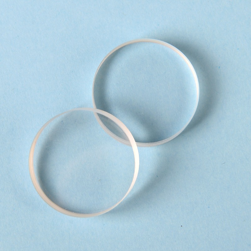
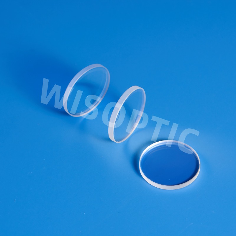
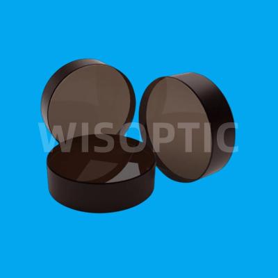
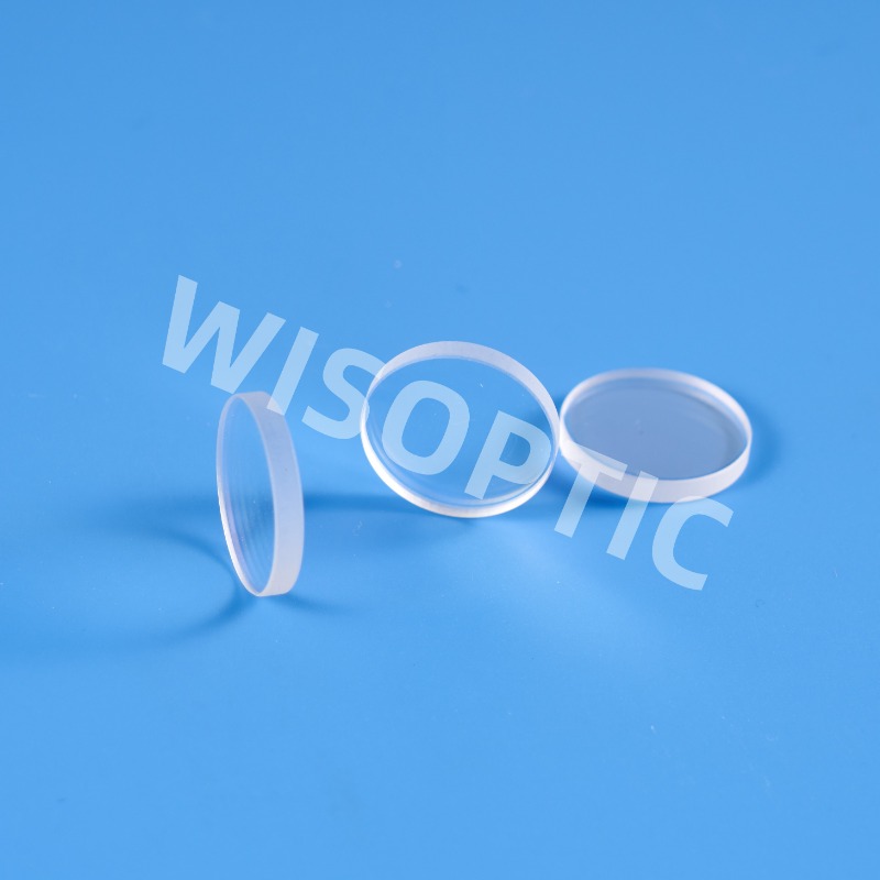
Polarization optics is important for both intra and extra cavity use. By having high contrast thin film polarizers in their design, laser engineers can save weight and volume within their devices without influencing the output. Compared with polarizing prism, polarizer has larger incident angle and can be made with larger apertures. Compared with polarizers made from birefringent crystals, the advantage of thin film polarizers is that they can be made in very large sizes, therefore can work in a laser device with high power or energy.
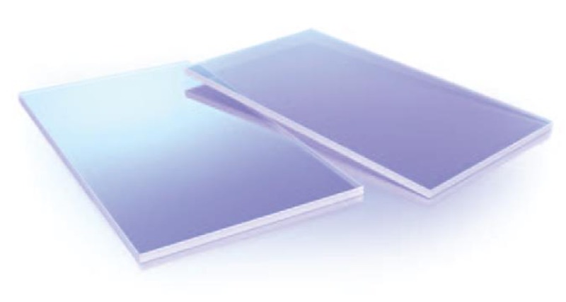
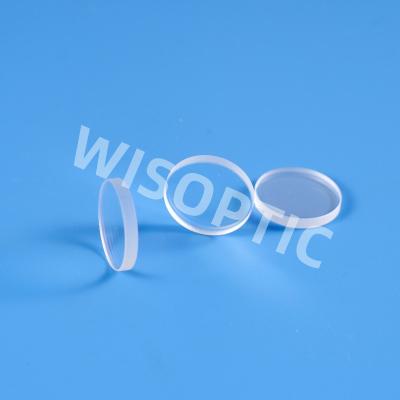
Thin Film Polarizers are made from composed materials which include a polarizing film, an inner protective film, a pressure-sensitive adhesive layer, and an outer protective film. Polarizer is used to change un-polarized beam into linear polarized beam. When the light passes through the polarizer, one of the orthogonal polarization components is strongly absorbed by the polarizer and the other component is weakly absorbed, thus natural light is converted into linearly polarized light.
WISOPTIC Specifications - Thin Film Polarizers
Material | BK7, UVFS |
Diameter Tolerance | +0.0/-0.15 mm |
Thickness Tolerance | ± 0.1 mm |
Clear Aperture | > 90% of central area |
Surface Quality [S/D] | < 20/10 [S/D] |
Transmitted Wavefront Distortion | λ/10 @ 632.8 nm |
Parallelism | ≤ 30” |
Extinction Ratio (Tp/Ts) | > 200:1 |
Coating | High LDT coating upon request |
Laser Damage Threshold | 10 J/cm² @ 1064 nm, 10 ns, 10 Hz |
Comparison of Different Materials of Polarizers
YVO4 | Calcite | Quartz | ||
Transparency Band | 500-4000 nm | 350-2300 nm | 220-3000 nm | 200-2300 nm |
Crystal Type (uniaxial) | Positive | Negative | Negative | Positive |
Mohs Hardness | 5 | 3 | 4.5 | 7 |
Thermal Expansion Coefficient | aa=4.43x10⁻⁶/K | aa=24.39x10⁻⁶/K | aa=4x10⁻⁶/K | aa=6.2x10⁻⁶/K |
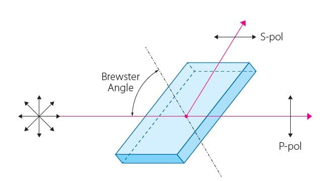
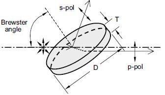
Thin Film Polarizers Optical Path Chart

